


In real terms, an industrial microwave dryer could reduce your drying cycles by 60% to 80%. But reality always shaves off 40% of that away due to poor layouts. Undersized power feeders. The wrong conveyor. Exhaust runs that are at loggerheads with the magnetron. PLC handshakes that jam the whole system. The bottleneck of the factory is rarely because of the dryer; most often it is due to the surrounding factory environment.
You know that microwave drying can give you throughputs that convection/direct air drying could never dream of. Do the rest of the production line also carry forth those savings or is it trapping it down via design? Our definitive guide handholds in the correct planning of a factory: floor space and utilities, RF safety zoning: SCADA integration-oriented. First, we go through the engineering basics, after which we delve deeper to discuss the industry-specific playbooks of food, pharmaceuticals, wood, and chemical operations as reference cases.
What Factory Layout Really Means for a Microwave Drying System
The factory layout of an industrial microwave-drying system deals with setting up the dryer in such a way and for such an environment, which will ensure smooth placement and safety as an integral part of the production line. The process focuses on each of the four tiers of planning, which change with each level.
At the equipment level, the cabinet size and location, the waveguide run, and the applicator are considered for correct microwave power application. At the process cell level, feeders supplying materials and those for cooling or packaging are interconnected. At the production line level, the cell is integrated with washing, sterilization, forming, or other unit operations. At the plant level, all utilities, hygiene zoning, and auxiliary services have to be planned in sync with new equipment.
The microwave-drying redefines the game, on every scale. Volumetric heating shortens dwell time, as a result of which a smaller dryer can be used with the increased coupling with its predecessors and successors-apparent aside-in comparison to what the hot air tunnel had called for. It makes the whole production cell quite tight, a piece of good news for floor space and bad news for layout architects who think the dryer should fit into the layout like a plug-and-play component.
See it in your facility: Send us your floor plan or process flow diagram and our engineering team will return a microwave drying system layout proposal within 5 business days.
Equipment Components and Their Footprint
Three crucial aspects involving an industrial microwave-drying system’s footprint include the sizes-or correct placement regarding the remaining items.
The Three Main Components
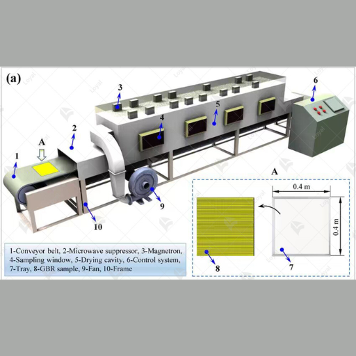
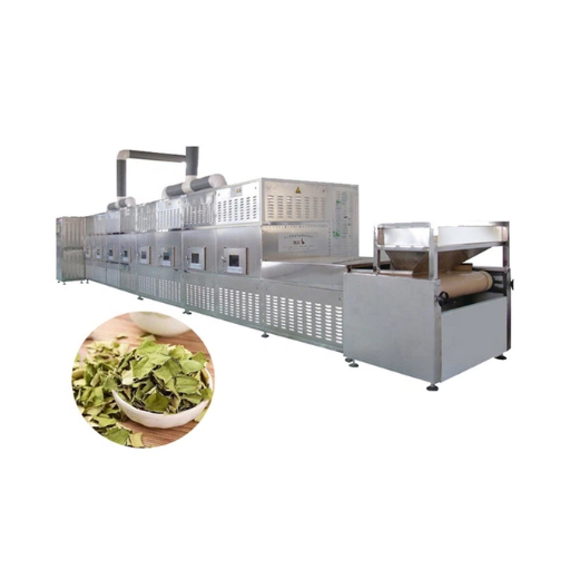
The crude microwave generator is enveloped into a rack system at times and may even stand entirely unassisted. These two options include magnetron-based units or the up-to-date solid-state systems. A standard generator of 50-100 kW does not eat up but a space of about 2 to 1 square meters. The waveguide can be a fabricated copper or aluminum portion guiding RF energy from generator to chamber; it must be installed entirely straight, with no sharp curls or obstructions placed in its path. Finally, one will come across the applicator, which is the location wherein the product meets with the microwaves, be it a multimode cavity, a single-mode cavity, or a planar applicator depending on the product geometry.
Footprint Examples by System Type
The footprint scales with design capacity and type of applicator; these should be used as a rough rule of thumb for planning purposes:
- Lab or pilot scale: 1.5-4 square meters (total footprint)
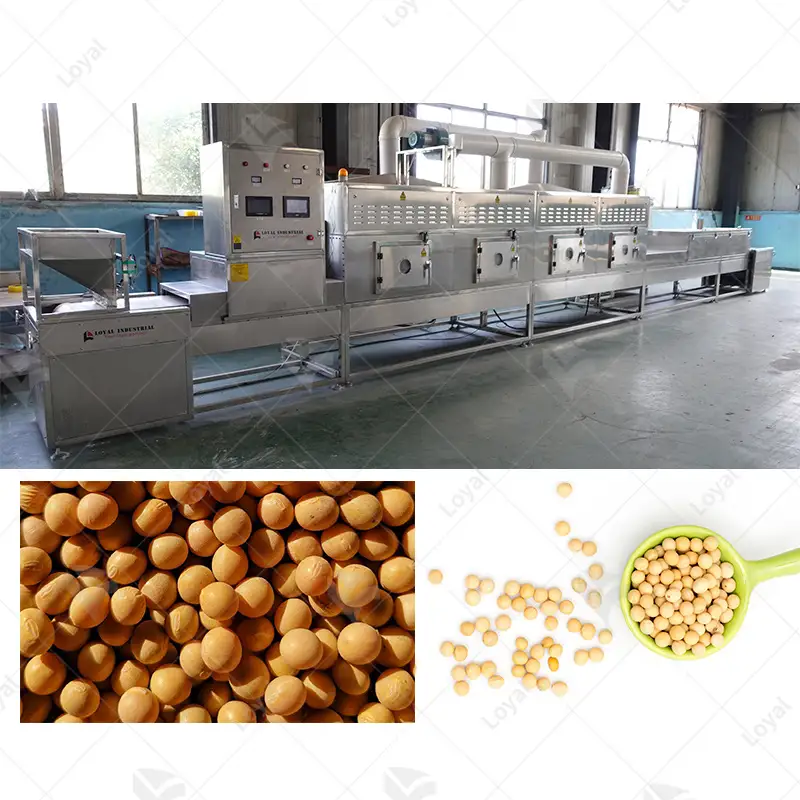
- Continuous belt (tunnel) dryer, for 50-150 kW: 8-20 m length; 1.5-3 m width
- Continuous belt, for 200 to 400 kW: 15-35 m length; 2-4 m width
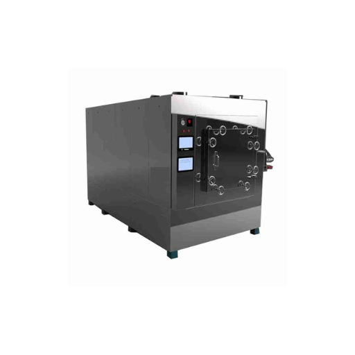
- Batch indexing system, depending on chamber volume: 4-12 square meters
- Modular skid-mounted multi-generator system: 30-60 square meters per skid, designed for staged expansion
Footprint Comparison: Microwave vs. Conventional Drying
A 500 kg/h drying line tells the footprint story clearly. The same throughput requires very different floor area depending on the technology you choose:
|
System Type |
Throughput |
Footprint |
Notes |
|---|---|---|---|
|
Hot air tunnel dryer |
500 kg/h |
80 to 120 m² |
Long dwell time means long footprint |
|
Freeze dryer |
500 kg/h |
150 to 250 m² plus utility |
Largest footprint, 10 to 24 hour cycle |
|
Microwave continuous dryer |
500 kg/h |
30 to 60 m² |
30 to 50 percent less than freeze, 50 to 60 percent less than hot air |
|
Microwave plus hot air hybrid |
500 kg/h |
50 to 80 m² |
Best balance for moisture-heavy feedstocks |
The footprint advantage is the single biggest reason plant managers consider microwave technology in the first place. It is also the easiest gain to lose. Specify the equipment correctly, then waste the saved space on poor utility planning, and you have shifted the problem rather than solved it. Our industrial microwave drying system 2026 complete guide goes deeper into how each system architecture compares.
Utility Planning Checklist for Microwave Drying
The “utilidor” present in most renovations represents a point of failure. Stacking drywall is straightforward until the dryer is lugged onto the site, cement is poured, and matter-of-factly, the existing electrical service really won’t handle the load. Think ahead for this feature!
With electrical power
Microwave systems will demand three-phase 380, 400, 415 or 480 V at 50 or 60 Hz, depending on your area. Size the feeder at the nameplate power in kW times 1.2 (this provides a safety factor) to allow for inrush and angle. Most installations also require a dedicated breaker and an isolation transformer for RF-grade systems, thereby ensuring that harmonic distortion does not occur on the shared circuits. For highly uninterrupted lines, develop a planned strategy for back-up power before the layout is finalized.
Cooling Water
Water-cooling systems for magnetron types need 8–25 liters per minute per 100 kW of generator power with 15–25°C inlet water temperature. Solid-state generator systems run cooler but also need chilled water closed-loop cooling for their power amplifier modules. Plan ahead for piping layouts and chiller capacity. Retrofitting the cooling lines through a completed plant is much more costly than designing these structures when the plant is being set up.
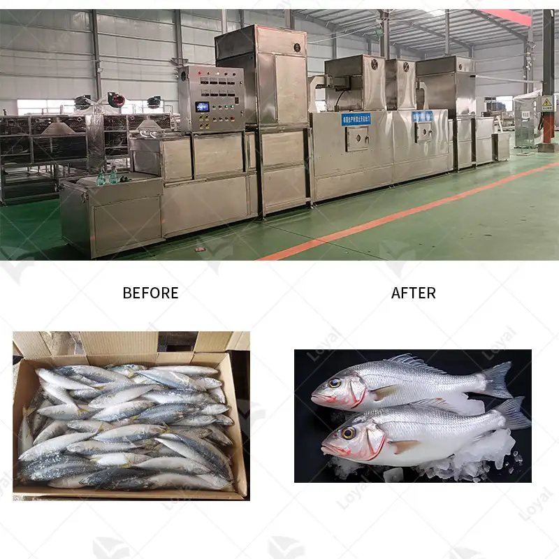
Ventilation and Vapor Extraction
To obviate possible dampening due to condensation of electronics and ancillary equipment, drying releases moisture vapor, which must be exhausted. Depending on the moisture content of products, 300-800 CFM per 100 kW is appropriate. Solvent and/or VOC-laden material demand scrubbers and ATEX compliance.
Air Compressed
Air serves pneumatic feed valves, vacuum venting for conforming systems, and pneumatic actuation diverters. Design for 50-150 SCFM of clean, dry air at 6-8 bar in the dryer cell.
Get these four streams correct, and the dryer reaches specification. Pry into another, and the line will stutter through commissioning with reduced throughput while you await utility upgrades.
RF Safety Zoning and Compliance
The federal regulatory framework for industrial microwave equipment in the United States is 21 CFR Part 1030, which limits leakage to 5 mW/cm² at 5 cm from the product surface. European facilities follow EN 60519 with broadly similar limits. Your layout has to respect both the technical limit and the operator-clearance reality that flows from it.
In practice, this means complaining about the applicator in the designated RF safety zone, with physical barriers, interlocked doors, and proper RF hazard signage to deter compliance with reasonable safety requirements. EMC compliances depend on waveguide chokes, RF gaskets, and door interlock mechanisms to seal the radio frequency while dangerously operating. The process shall be verified with a calibrated RF survey meter during commissioning and periodically thereafter.
Typically, there is a 1 m to 2 m operator exclusion zone from all sides while in operation. It is meant that service lanes shall lie beyond the barrier, while lockout/tagout points and water-cooling and pressure release piping, and the emergency stop shall all be reachable through switchverb or reposition; for pharma and food plants, the microwave cell frontside should lie in such a way that the RF safety zone does not encroach upon the HACCP or cleanroom cleanliness domains. Actually, both zoning systems can coincide, only if they are planned together.
Production Flow Integration: Where the Dryer Sits in the Line
A microwave dryer may act within three capacities in a production line. What role is fulfilled determines the layout. Pick the wrong role, and you will tear down the cell before the second year of operation.
What Microwave Dryer Can Do in Three Capacities
The full removal primary dryer deals with the drying down to full moisture with the longest applicator and highest power. The pre-heater (booster) lifts feedstock temperature preceding a hot-air finishing dryer, lowering the total cycle time without replacing the existing infrastructure. The post-heater (finisher) empties the last remaining bound moisture content by drying in after hot-air primary drying, and it especially excels for hot-air-hardening products.
A model of Yantai, a 500 hp fruit drying line, illustrates the choice. In 2024, when the team first scoped microwave drying-the retrofitting of the Yantai Highland Foods facility-planning aimed at a stand-alone rebuild to replace the existing hot air tunnel. However, upon simulation, the engineering team came to know that feed material enters at 78 % moisture; thus, the microwave dryer became a post-heater to remove the final 5 percent moisture. The hybrid configuration reduced the total drying time by 47 percent and waived the capital cost of a high-power microwave system. The lesson is that the role assigned to the dryer changes both equipment specifications and the size of the footprint by 30%-or even more.
Upstream Integration
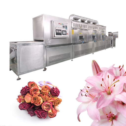
Feeding conveyors and feeding mechanism work as the control that starts the process of drying. For granular or small particle products, vibrating feeders are good choices. For petal products, sheet products and bulk product, belt conveyors work. Objects of powder are moved through screw feeders. With any of these options, the metering and dosing system should provide no excess or deficient metering since over- or under-metering reduces drying uniformity. Pre-treatment cells (washing, blanching, slicing, formation), antecedent to drying and appl i- calcate inlets, should be located within 5 to 15 meters to prevent cooling or re-wetting the product before arriving at the ap plicator.
Back-end Integration
For dried products, a temperature range of 50 to 80 degrees Celsius is observed at the outfeed of the applicator. In primary packaging, the cooling conveyor belt or, more preferably, a short cooling tunnel is in place to prevent condensation. Conveying the product out of the dryer makes use of the modular plastic belts or positive-driven stainless mesh conveyor belts for food while potentially resorting to metal belts in cases involving high-temperature materials. By virtue of their position nearby the dryer outlet, the inspection and sorting stations (moisture sensors, metal detectors, vision systems) should be designed such that their data feedback mechanism would be at the analytics interface between DSPC and the dryer. Maintain a smooth and continuous flow from one outlet to the next. Every meter of buffer adds floor space and re-handling cost.
Conveyor Interface Issues
Use microwave-transparent belts (PEEK, PTFE-coated, or some specialized polymer modular belts) inside the applicator. Mesh stainless is good in some applications but if frayed can cause an ark thus specification should include FDA-grade microwave-inert belts for food. All variable-frequency drives need to run together across the entire line to ensure even smack spacing throughout the drier. The overall line speed should not vary more than plus 3 percent because unbalanced drying is inevitable and even higher power settings hardly help.
See how a continuous microwave dryer integrates into a complete tunnel configuration, or compare against microwave drying versus hot air drying for hybrid planning.
PLC, SCADA, and MES Integration
Advanced industrial microwave drying systems are the control centers lying around not just any method for drying, but also far more widely linking MES to SCADA platforms. There is a control infrastructure now that does all-something, and therefore huge attention has to be paid to its layout.
By and large, they have a local PLC—Siemens S7, Allen-Bradley CompactLogix, or Mitsubishi FX/Q families—controlling applicator power, conveyor speed, temperature setpoints, and interlocks: the OPC UA or MQTT bridge the entire thing onto the plant-wide SCADA platform (Wonderware, Ignition, iFIX). This is the optimal time at which the integration of MES systems such as SAP ME or Siemens Opcenter must take place. Through recipe management, now, for example, you can input power profiles, conveyor speeds, and exhaust setpoints, so that you may recall them at whim during product line changes. The operators’ HMI should be placed wherein an operator could see both feed and discharge ends of the line without walking around the cell.
Alarm integration is commonly underrated as a layout decision by most engineering teams. In alarm inputs originating from RF leakages, magnetron temperatures, water flows, door interlocks, etc. at the radiation delivery system, all these must be presented centrally rather than at the local HMI. Predictive maintenance feed such as vibration, temperature, power quality data must be accommodated in networking drops and historian files right from the start and added to year phase; adding them later would involve cutting cabinets, pulling new cable runs, and retesting-again, most expensive.
Industry-Specific Layout Playbooks
Best design practices in layout are drastically different from one industry to another. The same example of a 200-kW microwave dryer appears before our eyes in significantly differently conceived cell concepts based on the product being produced.
Food processing
For food processing plants, they design according to HACCP zones: Both raw materials, in-process materials, and packing zones must have a physical separation. Placement of microwave dryers usually occurs at the juncture point between the in-process material and ready-to-serve clienteles. The design calls for 304 or 316 stainless steel, an applicator design that’s compatible with CIP, and an epoxy floor with drains.
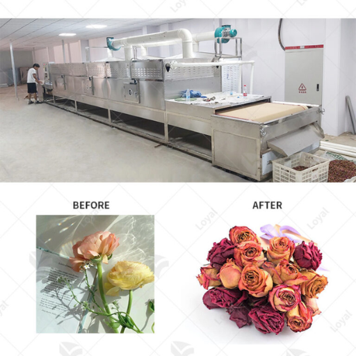
The layout pattern becomes evidenced by a black soldier fly larvae line. When Sarah Chen’s team operating from a Shandong BSF plant installed their first Loyal microwave drying line in October 2024, the cell was designed to be 38 m long: feed conveyor, wash station, dewatering screw, microwave dryer (8 to 12 min.), cooling take-down conveyor, and bagging station. Straight flow eliminated cross-traffic, even allowing two operators to run an 480-kg/h line per shift. A pilot line at a competitor’s facility used a U-shaped layout with the same equipment, but they had to employ four operators to ensure the same throughput because of the cross-aisle material handling.
Pharmaceutical
In pharmaceutical applications, the dryer is integrated into a controlled cleanroom environment with pressure cascades of HVAC air flowing into the processing area, usually at the ISO 7 or ISO 8 levels. Full IQ, OQ, and PQ validation requires utility schedules, drawing, and SOPs to match. A typical granule drying cell for tableting when it is in full swing will include a feed hopper, continuous microwave dryer, cooling tunnel, and blender feed in a U-shape in a layout around 25-35 sqm. The U shape is designed to minimize operator travel distance during validated operations.
Lumber and Wood
Wood and lumber drying all use big appliances that run approximately 8 meters to 20 meters in lengths. Consequently, the plant will exhibit a long and linear footprint. Material handling mostly uses carts or special lumber conveyors. The layout must provide forklift access for loading green lumber and unloading dried wood. For example, in one arrangement, an LVL manufacturer would send into pre-drying kiln capabilities and a fast microwave finisher rack, cooling tunnel, and grading line.
Chemical and polymer industries.
The following lines of text can be seen by all: From Europe it is referred to as an ATEX classification; from the US, a NEC Class I Division 2 classification. Dryers will need to be erected inside a classified zone, deploying explosion-proof electrical components. The addition of solvent recovery will require some extra room; hence, the placement of condensers, scrubbers, and waste collection skids will have to be near one another at the exhaust outlet. While many of those prevent the use of microwaves, engaging with the design team for layout was a solicited option; but where solvents are present-even though hazards are strictly minimized-machine users will need to spin ways outside the purview of the norms in order to thrive safely.
Ready to test the difference? Our microwave drying machine product line covers food, pharma, lumber, and chemical applications with industry-specific configurations.
Modular and Future-Proof Layout Planning
The best design choices during the present contribute to safeguarding you (or numerous milder whispers of his future self). Output volumes will rise; the mix of products might fluctuate; and the price of utility upgrades has been increasing yearly. The only way to curb some of such intolerables will be to plan such conditions into the design stage.
Make sure spare slots have been created from the beginning for an extra generator in either electrical room or in a cooling skid with standard development requirements for skid-mounted mounting. This design will effectively enable commissioning on a phase by phase basis, or even the shifted relocation of the modules to the next plant, upon review of business considerations. Leave for over-height waveguide overhead routings, and crane duties for magnetron replacement if the service technician finds it very hard to swap the storage device with a ceiling lying at a mere two meters above the machine beam.
The math pro pre-provisioning is quite clear. Usually, approximately 10% increased throughput will require about 15%-25% of an increase in floor space if not pre-planned; nevertheless, in the case of pre-provisioned, the same increased throughput could require only 5%-10% more floor space. The delta on utility upgrades is very large. Often, to retrofit three-phase service leads to expenditures 3-5 times larger than charging for the same service at install. Greenfield plants always have situations that work best for them, though even creative planning is necessary. The brownfield retrofits need a review of load, ceiling heights, and utility headroom before selection of equipment.
In Wisconsin, a brick-and-mortar plant orchestrated the proof in daylight. Reilly’s plant for bulk solids got a move on and had eight 50 kW solid-state microwave towers on the ready in 2025 with capacity having been preconfigured such that there were a couple of attachment points for the ultimate launch of two more ones. A surge in demand by 20% dating from 2026 wore the cap; stocking extra generators was made to only take eleven days to augment the given skid. In contrast, an operational plant that had worked to the last pound got all inched up for a boost in a further fourteen-week process: they had to get half of the electrical supply beefed up.
Common Layout Mistakes (and How to Avoid Them)
There are six main mistakes in the layout that account for most of the microwave systems’ commissioning delays that are seen in the development and startup phase of the project. Correct any of these and the line will start up clean.
- Feed and/or discharge congestion, caused by skewed conveyor-to-applicator power-profile speeds. Put VFDs for the entire line.
- Running waveguides through extremely active areas. Position waveguides above 2.5 meters or in covered zones so that neither workers nor forklifts can hit them.
- Mounting control cabinets far from the applicators. A long-haul distance like that (over 15 meters), other than introducing signal lag, will mean generalized additional wiring with no purpose.
- Sharing exhaust with general HVAC. Material versus wear can affect dryer performance, but chip through electronics inside the cabinet.
- Observing a proper operator workflow. An operator needs feed, discharge, and HMI at about 30-second walking distance. Poor layout will cause jams and stoppages.
- Setting utilities at the exact nameplate load. No headroom means no room for major utility upgrades.
A food processor in Anhui Province (so-named) had determined a 200kW microwave dryer in 2024 and thought of wiring the control cabinet at 25 meters circuit distance from the applicator to maintain a cleaner floor of production. Fiber-optic signal latency multiplied the time taken for the PLC handshake during high-speed indexing, crippling the team to rewire wiring and replace controllers in six months before the line finally put out the correct throughput. The dryer did fine. The layout didn’t.
Bringing It All Together
The microwave drying system gains such throughput and quality benefits only if the factory around it is built to support it. Footprint, utilities, RF safety, conveyor integration, and SCADA handoff should all be gathered before equipment even hits the site, needing meticulous planning. A 30-minute layout review with an accomplished microwave engineer at the design stage can save a six-figure expense for prohibitive change orders.
Success of a factory layout for microwave drying systems is marked by driving five key points:
- Plan for the footprint, to be rooted in throughput rather than equipment choice, while examining microwave, hot air, freeze, and hybrid options at the same target throughput.
- Empower with provision of utilities for power, cooling water, exhaust, and compressed air at the inception of the design, allowing for 20 percent in headroom for future growth partnering where it becomes Fed Reg.
- Zoning standards for RF safety flow under 21 CFR 1030 should be married to integration with HACCP, cleanroom, or ATEX zoning, not battle against it.
- The production integrated control decides if the drier is working as a primary dryer, pre-heater, or post-heater, ultimately shaping the cell layout.
- Install modular for provisioning will lower costs in the range of 50–60% for any future expansion as opposed to retrofitting installed conditions.
Send us your floor plan or process flow diagram and our engineering team will return a microwave drying system layout proposal, including utility schedules, footprint dimensions, and integration drawings, within 5 business days. Contact our team to start the assessment, or browse the full industrial microwave dryer buyer’s guide to compare equipment options before you commit to a layout.